4.5.2 Example
Configuring VXLAN for vCloud Director 5.1 requires the initial preparation of the vCloud Networking and Security network virtualization settings. This configuration is executed outside the vCloud Director 5.1 management interface.
The following figure shows the preparation and configuration of vCloud Networking and Security in a single cluster. The following procedure is applicable to any number of cluster configurations.
To prepare and configure vCloud Networking and Security in a single cluster
1. Log in to the vCloud Networking and Security management interface.
2. Select the Datacenter object.
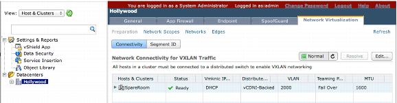
3. Click the Network Virtualization tab, and click the Preparation link. This reveals the Connectivity and Segment ID configuration tabs.
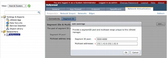
4. Click Edit, and enter the segment ID pool and multicast address for vCloud Networking and Security to use to provide the VXLAN network segmentation. The segment IDs cannot be mapped directly to any one multicast address as the possibility of one-to-one mapping does not exist. This segment ID and multicast address configuration is defined in ranges.
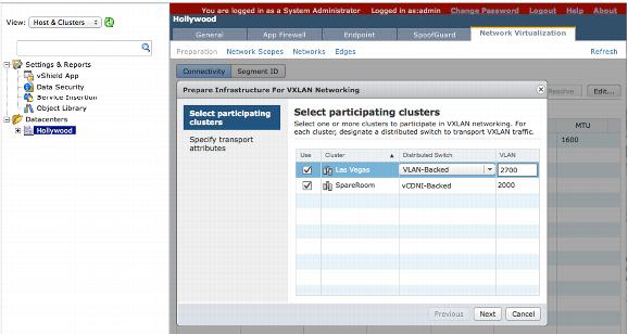
5. Click the Connectivity button under the Network Virtualization tab to prepare the resource clusters that will be part of the vCloud Director 5.1 VXLAN segments.
6. Choose the distributed switch that is to be associated with the resource cluster, and enter the VLAN ID for the network segment to use to overlay the VXLAN traffic coming from the distributed switches.
7. Perform the following configuration on the physical Layer 3 switches or routers:
 Enable multicast routing on the
 routers.
Configure IGMP Snooping on the switches.
If VXLAN is being used in a single VLAN, enable IGMP Querier and IGMP Snooping on the physical switches.
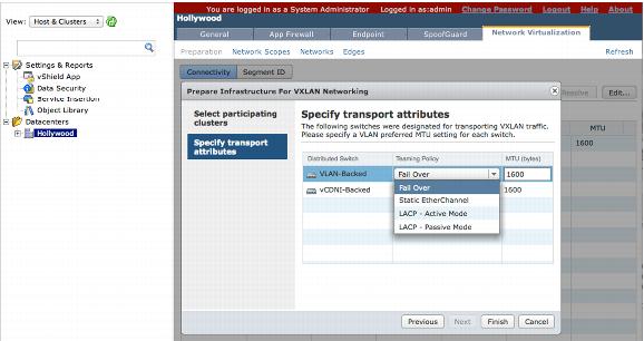
8. Specify the NIC teaming policy that applies to the respective distributed switch configuration, and MTU settings. The MTU settings for VXLAN default to 1600 bytes due to the VXLAN ID encapsulation technique, which increases the size of the packets. This behavior is similar to the VCDNI requirements in vCloud Director—VCDNI required a minimum MTU packet configuration of 1524. You must either use jumbo frames or increase the MTU across all network devices.
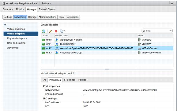
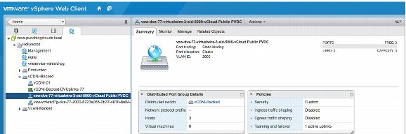
After configuring the settings for the distributed switches, the VXLAN VMkernel modules and VMkernel NICs are deployed and configured onto all members of the cluster. New dvPort groups are created and automatically added to the distributed switch associated with the VXLAN configuration.
The new dvPort group and VMkernel interface can be identified by their unique naming convention vxw-vmknicPg-dvs-xx-xx-xx-xx. The deployed VMkernel modules and VMkernel NICs act as the Virtual Tunnel Endpoint (VTEP) that is used to perform VXLAN packet encapsulation and decapsulation.
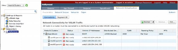
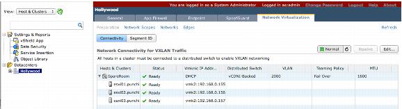
9. Apply IP addresses to the newly created VMkernel interfaces with DHCP.
All of the newly created VMkernel interfaces receive IPv4 private addresses within a 169.254.X.X/16 segment, unless a DHCP server is accessible on the network segment used for the VXLAN. If a DHCP server is not accessible, the configuration status of the hosts is displayed as Not ready in the Status column.
If the configuration is correct the Status is displayed as Ready.
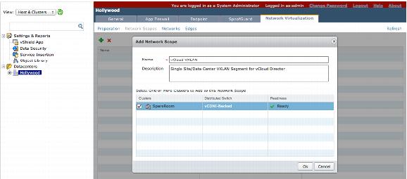
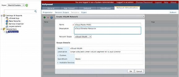
10. Click the Network Scopes link to define the network scope. Provide a Name and Description, and choose clusters to be part of the segment.
11. Create the logical network to be consumed beyond IEEE 802.1Q standards restrictions. Click the network link to create logical networks (also known as virtual wires). Provide a Name and Description, and choose the desired network segment.
12. At this point, you can identify the segment IDs and multicast address of the created logical network. A new port group is automatically created for every logical network.
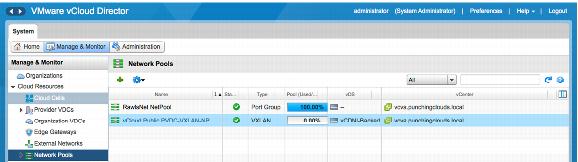
All of the required vCloud Networking and Security Manager network preparation to use VXLAN with vCloud Director 5.1 is done. vCloud Director automatically enables VXLAN and creates a VXLAN network pool when a provider virtual datacenter is created.
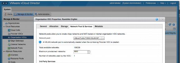
To see the configured options for a VXLAN network pool, go to an organization virtual datacenter’s properties, and under the Network Pool & Services tab select the VXLAN network pool.