4.4.2 Example
In this external network example, the service provider uses existing network automation software to dynamically provision the vSphere and corresponding vCloud Director networks. The service provider uses an automation platform to dynamically automate the following tasks during customer onboarding:
 Provision a vSphere
 p
ort group on the dvSwitch for each customer.
Assign an appropriate VLAN to this p
ort group
for each customer.
NoteThe external network can be differentiated through use of a separated physical network or VLAN. If using VLANs, only a single VLAN can be used on the port group.
Provision a dedicated vCloud Director external network and map it to the p
ort group created in step 1 for each customer.
Create a d
irect c
onnect e
xternal o
rganization network for each customer.
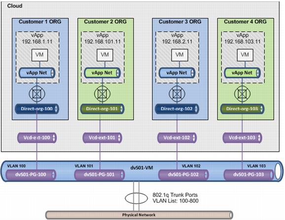
Figure 9 shows a VLAN configuration that uses
802.1q VLAN trunk ports on the physical switches to the ESXi dvSwitch uplinks.
This enables the physical switching infrastructure to allow all the VLANs configured in the infrastructure to communicate to the ESXi hosts while still keeping the VLANs separated and in separate broadcast domains.
The dvSwitch delivers
the appropriate Ethernet f
rames to the appropriate p
ort g
roup based on a match of the VLAN t
ag on the frame and the VLAN associated with the p
ort group.
The dvSwitch p
ort groups remove the VLAN tag from the Ethernet frame and deliver it to the appropriate virtual machine.
This architecture is commonly referred to as Virtual Switch Tagging (VST).
In the figure, four organizations are shown: two have vApps direct connected to the parent organization network, and two have a vApp network connected to the parent organization network.
Figure 9. Service Provider External Network Example
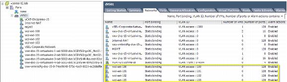
The vSphere c
onfiguration to support this architecture requires separate dvSwitch p
ort groups for each customer and a VLAN provisioned for each.
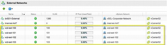
Figure 10 and Figure 11 show four customers
configured in this environment.
Figure 10. vSphere Port Group Configuration
Figure 11. vCloud External Networks
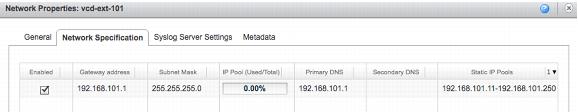
Figure 12 and Figure 13 show the n
etwork s
pecification for one of the customer vCloud external networks (vcd-ext-101).
A n
etwork specification represents a subnet and its associated configuration for the external network.
Figure 12. vcd-ext-101 External Network Configuration
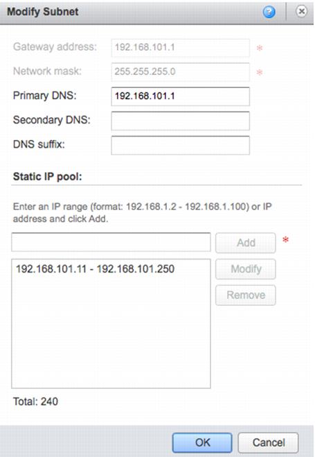
Figure 13. Network Specification Properties
In this example, a static IP pool was configured providing a total of 240 IP addresses. vCloud Director allows multiple static IP pools for each external network. These addresses can be used for assignment by vCloud Director to virtual machines or external interfaces of the vCloud Networking and Security Edge devices. The gateway address in this configuration is 192.168.101.1, which is a logical interface on the Cisco Layer 3 switching infrastructure.