Device | Location | IP Address | Notes |
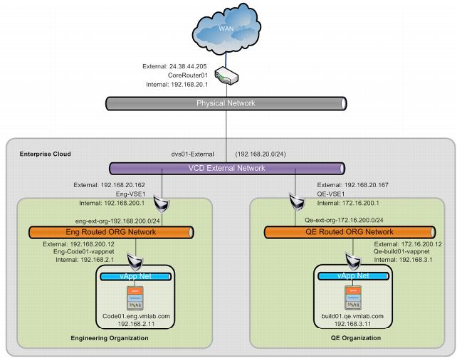
Corerouter01 | Physical network perimeter | 192.168.20.1 24.38.44.205 | Cisco ASR No static routes defined Gateway for physical network to Internet |
QE-vse1 | VCD system virtual datacenter | Internal: 172.16.200.1 External: 192.168.20.167 | vCloud Networking and Security Edge 5.1 QE external organization network |
Eng-vse1 | VCD system virtual datacenter | Internal: 192.168.200.1 External: 192.168.20.162 | vCloud Networking and Security Edge 5.1 Engineering External organization network |
QE-build01-vappnet | VCD system virtual datacenter | Internal: 192.168.3.1 External: 172.16.200.12 | vCloud Networking and Security Edge 5.1 qe-build01 routed vApp network |
Eng-code01-vappnet | VCD system virtual datacenter | Internal: 192.168.2.1 External: 192.168.200.12 | vCloud Networking and Security Edge 5.1 eng-code01 routed vApp network |
Build01.qe.vmlab.com | QE organization | 172.16.200.11 | Ubuntu 11.10 |
Code01.eng.vmlab.com | Engineering organization | 192.168.200.11 | Ubuntu 11.10 |