4.1.3 Example
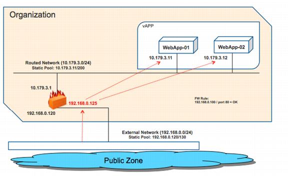
The Edge Gateway is connected to one side to the vCloud Director external network, which connects directly to the Internet. It is also connected to two routed organization virtual datacenter networks. Our focus is on the network named “Org-External-Routed-Internet” because this is where the Web servers to be load balanced are connected.
Table 9. Network Device Information
Device | Location | IP/Netmask | Notes |
Internet-NAT | External network Static IP pool | 192.168.0.0/24 192.168.0.120–130 | Class C network 10 public IP addresses |
Org-External-Routed-Internet | Organization virtual datacenter network Static IP pool | 10.179.3.0/24
10.179.3.11–200 | Class C network
190 internal IP addresses |
Edge-Gateway | COE organization | External: 192.168.0.120 Internal: 10.179.3.1 | Internet-NAT Org-External-Routed-Internet |
WebApp-01 | COE organization | 10.179.3.11 | Guest IP address |
WebApp-02 | COE organization | 10.179.3.12 | Guest IP address |
Figure 7 shows the components of a typical load balancing arrangement. Figure 7. Graphical Summary of Components
To create load balancing with vCloud Networking and Security Edge
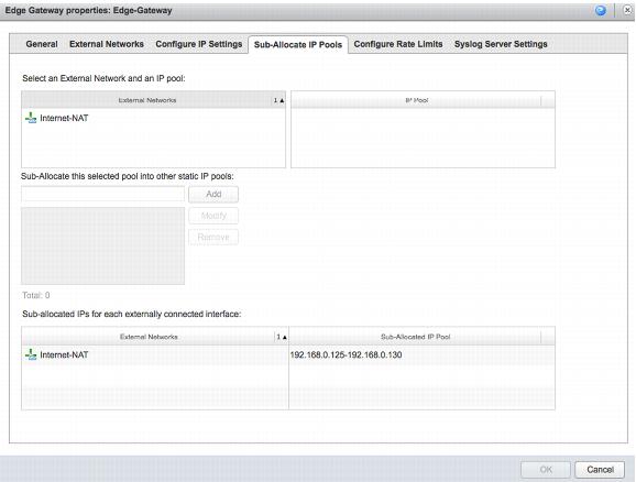
1. To create a load-balancing rule the organization administrator must use a public IP address from the external network that was preallocated by the vCloud administrator. In this example, the vCloud administrator reserved for this vCloud Networking and Security Edge instance the public IP address range 192.168.0.125–130 as indicated in the vCloud Networking and Security Edge Gateway properties. One of these reserved IP addresses will be used later as the virtual IP address.
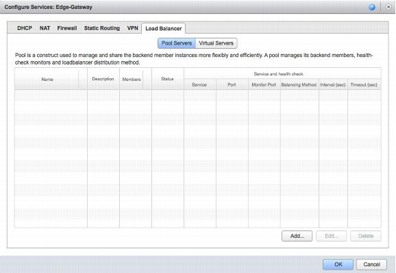
2. Open the vCloud Networking and Security Edge Gateway services page and click the Load Balancer tab to configure the load-balancing rule.
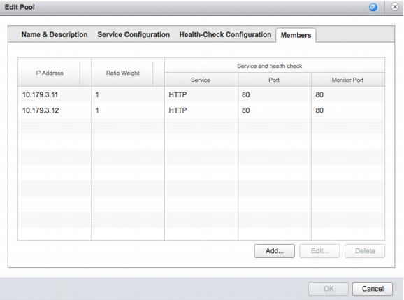
3. Click Pool Servers. List the Web servers that are to be load balanced.
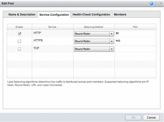
4. Configure the two Web servers in this pool and use the vCloud Networking and Security Edge Gateway to balance HTTP traffic from the virtual server to the Web servers on destination port 80 in a round-robin.
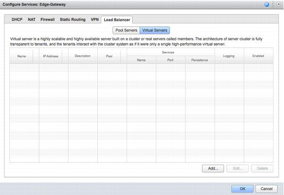
5. Now that a pool of servers is configured, a virtual server can be configured from the following view of the Load Balancer tab.
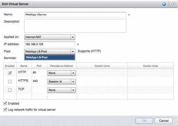
6. Y
ou can configure a new virtual server to use by selecting the previously defined pool and allowing the services you want
(Figure 7).
This is the pool we created in the previous step and that contains the two front
end W
eb servers. When the configuration is finalized, this new virtual server is displayed in the Load Balancer page of the vCloud Networking and Security Edge Gateway services.
Note: The 192.168.0.125 IP address used in the example is one of the public IP addresses (on the external network) assigned to this vCloud Networking and Security Edge instance. This is used to create a load balancing rule that leverages the vCloud Networking and Security Edge DNAT capabilities.
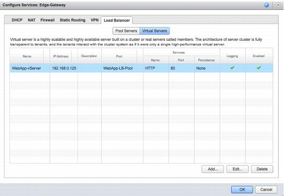
7. Confirm that the virtual server was created as intended.
At this point, connecting from outside the organization to http://192.168.0.125 results
in the vCloud Networking and Security
Edge Gateway balancing
in round-robin the two Web servers with IP addresses http://10.179.3.11 and http://10.179.3.11 respectively.
This load balancing configuration was done at the vCloud Networking and Security Edge Gateway level, backing the organization network. This configuration is not possible on the vCloud Networking and Security Edge device backing a vApp network.